Home Facts History Gallery Blog Videos Events Links

Nene Valley Railway, Wansford Station, Stibbington, Peterborough, PE8 6LR

Tel: 01780 784444

October 2017

6th November 2017.  

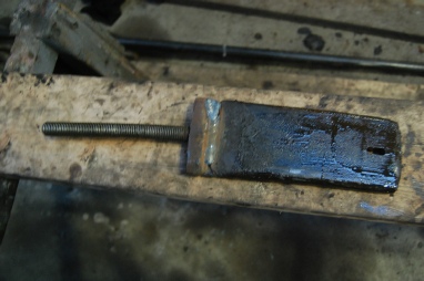
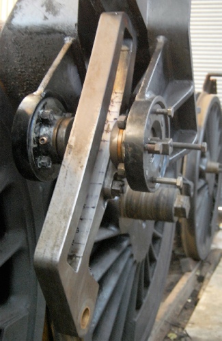
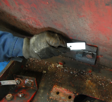
One of the big jobs around the motion is the extraction of the wedges that secure the crossheads to the piston rods.  This is achieved by welding a screw thread to the top of the wedge and then using a 'bridge' against which a nut is tightened to extract the wedge.  Serious force is required to start the release but once the initial grip was broken, the RHS came out quite smoothly.  The LHS fought all the way and when finally out, the wedge was seen to be 'banana' shaped.  Inspected later in the day by a visting engineer, he opined that it was the result of priming in the LH cylinder, confirmed (he said) by the 'step' that could be felt at the leading edge of the hole through the crosshead/psiton rod.

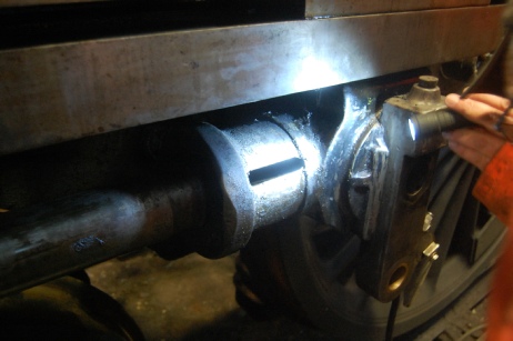
The second part of this job is to release the taper-pin seating of the end of the piston rod in the crosshead.  The prescribed method for this task is to use a special hydraulic tool but, in preservation, it's become common to use either a button/wedge combination or a screw through an old gudgeon pin.  In preparation for the second of these, a suitable screw has been machined for use next week.

A bit of tidying up around the outside of the cylinders has been done - the final section of cladding was removed by new-boy Roger and the remaining fittings have been taken off the cylinders by the front-of-chassis team - supports for the pressure relief drains that run down from the piston valves.

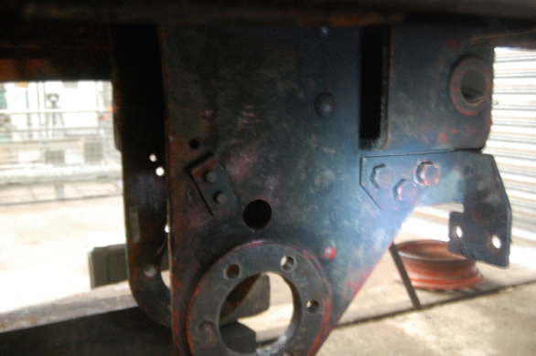
Under the footplate, battle commenced with the bracket that holds the hinge for the brake actuation.  Brute force (Philip, with Ian & David) removed the first 2 (of 16) bolts and, on Sunday, Alan used heat and force to take out a further 4.  That leaves two outers to come off, then a very difficult-looking 8 internal bolts - these might be simply burned off.  What can be seen of the drag-box under the (now removed) steam-brake cylinder and around the hinge bracket is giving some cause for concerned - it looks very corroded and thin in places.

Outside on the boiler, at the front end, StanD and Dennis have been knocking soot and scale and rust out of the insides of the superheater flue ends to ease the job of the oxy-acetylene cutting that is needed to remove those tubes.  Inside the firebox, very good progress has been made removing the soot and exposing the copper of the inner box.  The insurance NDT of the boiler is scheduled for Tuesday November 28th, so we've a couple more weeks to be as ready as we can be for that.

Banana-shaped wedge from LH crosshead

Crosshead with wedge removed

Brake actuation bracket.  Held by 16 rust-headed bolts to the bottom of the dragbox.

December 2017

10th November 2017.  

Highlight of the week was the crosshead/piston rod separation going far easier than anyone anticpated. Well done to DOC who make the great big, non-standard, screw and to Paul et al who had courage to attempt what everyone said was nearly impossible, fraught with danger and involved loud noises.   There's some head-scratching trying to understand why it was so straightforward and yet more thinking & research to make sure we put it back together properly.  With the rod/crosshead separated, it was a fairly quick job to get the pistons out so now they and the complete cylinders are exposed and more measurements can be taken to help us decide what is reusable and what needs replacement.  Roger and Ken have started the complicated-looking dismantling of the expansion link brackets.

Less glamourous but still hard work is the brake linkage bracket under the footplate.  Phil, Ian and David, often with an audience of thousands, attacked and removed/destroyed the remaining 10 bolts but the bracket remains stubbornly attached to the drag box.  Wedges and jacks are proposed for next week.

Outside, Graham B took the final handrail standoff off the boiler - how it came to stay fixed for so long is a mystery.

Getting started with the component overhaul was a bit slow - Martin and Dave showing how it can be done with needle-gun and gritblasting.  StanD applied his special talents to de-gunging the brush-safe and cleaning the brushes that had sat there since they were last used.  I've located a heater (and Kingsley has a spare) to keep the studio at a temperature OK for painting.

Looking forward down the LH cylinder. Note the scratches where broken rings have rubbed against the cylinder wall.

Part-removed expansion link. The numbered marks are the points at which the gap is to be measured. Note how the upper part of the link is dirty but the lower section is shiny.   We don’t know why - maybe uneven wear due to misalignment, or perhaps just that the top end is usually hidden under the running board, so doesn’t get cleaned!

19th November 2017.  

Lots of normally hidden stuff this week.  Pistons out, expansion links down, expansion link bearings exposed.

First, the pistons.  The BR drawings show a piston with two rings separated by a relatively wide gap.  Our pistons have 3 equi-spaced rings. The rings themselves had all suffered breakage to some degree, a couple were in fragments (some of which had already been found in the cylinder cocks!)  The 3-ring design is believed to be a Southern-region modification (Test T2272) made around 1959/60 in an attempt to improve steam tightness and reduce breakages (!).

Secondly, the expansion links. These appear quite worn, the ‘loops’ at each end are very shallow, suggesting that the slides have been ground out at some stage.  Careful measurement and reference to MT276 is needed to determine whether these can be re-used.

Thirdly, expansion link bearings.  Something is badly wrong here.  It looks like a complete lubrication failure and we’ll need some new pieces of phosphor-bronze to replace these.

RH piston, showing 3-grooves for 3 rings.

The two nuts were loosened before the piston rod was freed from the crosshead, to give a strong hold against which to turn the nuts.  One (the thin one) is a LH thread, the other is RH.  A thin washer separates the two nuts and the whole assembly delivers a very firm hold of the piston on the rod.

Expansion links, Left and Right

Expansion link bearing. Dreadful scoring inside the bush.  The matching part is equally distressed.

28th November 2017.  

As well as the exciting motion disassembly, more mundane matters continue to be attended to.  

When pipes were being taken down, focus was correctly on labelling and recording the routing of them.  Now we need to get all the brackets and clamps away from the frames, so that both they, and the frames, can be made ready for painting.

Not particularly photogenic, a couple of examples are featured.  Just look at the state of the frames - some serious cleaning is needed before the paint can be removed with needle-guns.


Component 73935, the curved piece on the right, already has its tag affixed. The piece on the left will also be tagged before removal to the container and eventual cleaning and repainting.

Trying to be helpful, the fitters hand has managed to angle the tag so that the number cannot be read. Fortunately it has been logged, so we know where it goes.

Parts removed count:

936